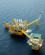
Producing natural gas and mineral oil
Biomass – millions of years old
Natural gas and oil form over hundreds of millions of years from dead organic material that has accumulated on the bottoms of seas, lakes and swamps. Oil is formed primarily from dead microalgae, or phytoplankton, while coal and natural gas derive mainly from land plants. Especially large amounts of biomass accumulate in warm regions with lush vegetation or prolific algal growth.
Dead biomass normally decomposes in water where it is broken down by bacteria into carbon dioxide and water. This process consumes oxygen. With the input of large amounts of biomass, oxygen can be completely depleted by the bacteria. This creates oxygen-free zones where decay no longer occurs.
Thus, over time, packages of biomass several hundred or thousand metres thick can accumulate on the sea floor. Whether natural gas or mineral oil is formed from the biomass depends primarily on the temperatures at these depths.
Plankton cooked down to oil
Oil deposits formed through a series of consecutive processes. First, the phytoplankton accumulated on the sea floor. Together with fine rock and clay particles washed into the sea from the mountains and flatlands, the algal biomass was transformed into an organic-rich sludge.
Over periods lasting many millions of years, so much of the organic sludge was deposited on the sea floor that, due to its enormous weight, it gradually changed to claystone and was finally compressed and hardened into a clay-rich shale. Even today it can be said that, to some extent, in these porous shale layers at depths of 2000 to 4000 metres and at temperatures between 65 and 120 degrees Celsius the transformation of biomass into oil is taking place. This temperature range is called the “oil window”. Just like in a chemistry laboratory, the biomass here cooks down into a broad range of chemical compounds that are composed exclusively of carbon and hydrogen, and are thus referred to as hydrocarbons.
Crude oil is therefore a mixture of hundreds of different compounds that are initially separated in refineries or split into smaller molecular chains. The splitting process is referred to as “cracking”.
Not only are fuels such as petrol and diesel produced from the crude oil. Other products of the refineries include ethylene gas and propylene gas. The tiny hydrocarbon molecules of ethylene and propylene, which contain only a few atoms, are used in plastics production and many other applications.
The shale and other rocks in which oil forms are called oil source rocks. They contain up to 20 per cent organic material. Over millions of years the source rocks have gradually been compressed by the sediment and rock layers being deposited on top of them, resulting in the formation of oil. As increasing amounts of oil formed, more of it escaped from the source rock and rose slowly through the overlying rock and sediments. In some areas it even reached the surface. Near the northern German city of Celle, for example, tar pits formed naturally, containing a black liquid which, historically, has been used as lamp oil, a lubricant, and even as a natural remedy.
- Oil reservoirs were formed whenever the upward travel of the oil was blocked by impermeable materials such as salt or clay layers. If these impermeable layers were underlain by a porous reservoir rock such as sand or limestone, it acted as a sponge, causing the oil to accumulate. Specialists call these formations underground trap structures. In addition to oil and other hydrocarbons, the porous rocks also contain large amounts of water, which has to be separated out during production of the oil.
Because the continents, as a result of continental drift, have been moving for millions of years or more, the ancient seas in which the shales were formed no longer exist today. At a time around 120 million years ago, South America and Africa began to break apart. Initially a small tropical sea surrounded by land was formed in this process, in which a large volume of biomass was deposited. This sea then expanded to become the South Atlantic Ocean. Today the ancient sediments of the former tropical sea lie off the coasts of South America and West Africa.
- 1.15 > 300 million years ago extensive clubmoss and horsetail forests were common. The plants were several metres high, much taller than today. Coal and natural gas were formed from them.

Peat
Peat is defined as soil that contains more than 30 per cent organic material. This consists of partially decayed plant remains that could not be completely broken down in oxygen-free, standing swamp water.Layer upon layer of peat
As a rule, natural gas is formed from terrestrial vegetation that once grew in flat coastal areas or in near-coastal swamps in subtropical and tropical climates. In swampy areas, peat usually formed first. Due to numerous cycles of sea-level rise and fall over the millennia, these wetland areas were repeatedly flooded. Fine sand and clay particles that were transported from the land to the sea were then deposited upon the submerged peat layers. When the water retreated with falling sea level, land plants colonized the areas again, allowing a new peat layer to form.
Over millions of years, the rising and falling of sea level created a layer-cake sediment pattern in which sandy and clayey layers alternated with thick peat layers. Ideal conditions for the formation of peat were present in large regions of central and northern Europe and in North America during a period from 290 to 315 million years ago. At that time these regions lay close to the equator. They were located in a warm, tropical zone, and were rich in vegetation. Not until later did these land masses drift several thousand kilometres northward to their present position.
With time, the layer-cake structure of alternating peat and clay layers was also covered by new sediments and compacted by their enormous weight. However, no oil was formed from the old peat layers, but first lignite and later hard coal. At a depth of 4000 to 6000 metres and temperatures between 120 and 180 degrees Cel- sius, natural gas formed in the coal over many millions of years. For the formation of natural gas, higher tempe- ratures are required than for oil.
- As a rule, natural gas contains around 90 per cent methane. This is accompanied by other gas-phase hydrocarbons such as ethane, propane and butane, as well as non-flammable gases such as carbon dioxide and nitrogen. An additional component is hydrogen sulphide, which has to be removed from the natural gas before it can be used. Hydrogen sulphide can convert to acid when the gas is burnt, which can lead to corrosion in power plants and heating systems.
Natural gas with an especially high content of hydrogen sulphide or carbon dioxide is called acid gas. If this is to be used it must undergo extensive cleaning. Natural gas also migrates gradually out of the source rock. If it is not trapped by dense rock layers then, like oil, it can rise all the way to the Earth’s surface. The “eternal fires” in Iran are fed by rising gas and condensate, and were presumably lit initially by a lightning strike. There are many places around the world where fires fed by underground gas are still burning. Many of these were venerated by ancient cultures and have become sacred sites.
Wherever underground trap structures were present, the natural gas, just like oil, could accumulate in reservoirs. Generally, the accumulations are only considered to be reservoirs when they are large enough and the rocks permeable enough to make production of the hydrocarbons economically feasible. This is equally true for both gas and oil.
Gas or oil accumulations that are too small to be economically produced, however, occur much more frequently in nature.
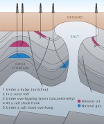 1.16 > Gas and oil accumulate in various kinds of underground reservoirs.
Natural gas and oil trapped
Specialists distinguish different kinds of reservoirs in which large amounts of natural gas or oil have accumulated. Typical reservoir types include: ANTICLINE: An anticline is an arching structure of rock layers, a kind of underground hill. It is formed when dense rock layers undergo pressure from the sides caused by movement of the Earth’s crust. When the anticline is composed of impermeable rocks, the rising gas and oil can accumulate there, as in an inverted bowl. FLANK OF A SALT STOCK: Salt stocks are large underground accumulations of solid rock salt that can be as much as thousands of metres thick. If an impermeable rock layer (a trap structure) abuts on the flank of a salt stock, then ascending oil and gas will be trapped between the rock layer and the flank, because the salt is also impermeable. UNCONFORMITY: An unconformity arises at locations where rock layers abut obliquely, or at an angle to one another. Unconformities are formed by lifting, subsidence, or squeezing of rock packages that are subsequently overlain by younger sediments. If these overlying sediment layers are impermeable, ascending gas and oil can accumulate and concentrate in the underlying rock packages. CORAL REEFS:In many instances, natural gas and oil collect in very porous limestone that has formed from ancient coral reefs. SALT STOCK OVERHANG: Some salt stocks are mushroom-shaped with a wide dome at the top, which forms a kind of umbrella, known as the overhang. Gas and oil can accumulate beneath this. Salt stock overhangs are mainly the result of immense underground pressure. Salt rises because it is less dense than the overlying strata. It bulges upward into domes or the mushroom-shaped overhangs. These movements are referred to as salt tectonics.
Seeking natural gas and oil
The fact that there is still enough natural gas and oil in spite of globally rising energy demand is in part due to the discovery in recent decades of new reservoirs on land and in the sea, largely as a result of the development of new methods to detect the reservoirs. The search for resources involves both prospecting and exploration.
Prospecting is the search for unknown reservoirs. The stage of prospecting is followed by exploration, which involves the precise appraisal and development of the reservoirs and resources that have been found. If deposits are discovered during exploration, then additional wells are drilled to estimate the size and dimensions of the reservoir. This is the assessment phase. If the found reservoir is large enough then production can begin.
Prospecting begins with a determination of whether gas and oil can be expected to occur in a certain area. This includes an initial collection of data relating to the deep rock strata in order to determine the geological development of the area in question. Computer programs called basin analysis systems are employed to play back the geological history of the region. These programs simulate the millennia of sedimentation in the prehistoric marine basin and the transformation at great depths from sediments to rocks. The formation of fractures, trap structures and salt stocks, and the effects of movements of the Earth’s crust due to continental drift are also simulated by such programs.
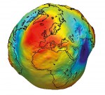 1.17 > The strength of the Earth’s gravitational field varies at different locations. It depends primarily on the density of the rocks. Very accurate gravity maps have been created in recent years with the help of satellites. In this figure, areas with strong gravity values are shown in red and are slightly raised. Regions with weaker gravity are blue and are shown as depressions. Scientists call this image the “gravity potato”.
- This is followed by extensive geophysical studies, in which the subsurface is examined similar to the way a patient is x-rayed during a medical examination. In principle, the same methods are used on land and in the sea. For investigations at sea, however, aircraft, ships, and special additional equipment are necessary. Important geophysical methods include: SEISMICS: Seismics are the most important prospecting tool deployed all over the world. The methods work in a manner that may be compared to ultrasound examinations by a doctor, in the sense that ultrasound waves are sent into the body from a transducer probe and are reflected at different intensities by various organs or bones. The ultrasound machine creates an image of the inside of the body from the pattern of reflections detected. With seismic methods, acoustic waves that penetrate into the sea floor are transmitted by airguns on a research ship. The waves travel at different velocities depending on the type of rock they encounter. In the subsurface they are reflected at the boundaries between different rock types. From the specific differences in the sound waves’ travel times, a computer can draw conclusions about the nature of the rock forming the seabed. Just a few decades ago seismic methods could only provide simple cross sections of the sub-bottom. Today modern 3-D seismic methods are employed. These are largely made possible by increasingly powerful computers that are capable of spatially representing bottom structures and reservoirs (Chapter 3). GRAVIMETRY: Gravimetry was one of the first geophysical techniques to be used in the search for oil and natural gas. This method utilizes the Earth’s gravitational force, which is not equally strong everywhere. That force rather varies with the mass of the materials in the ground at a given point, which depends in turn on the density of the rocks. Gravity measurements can be used to distinguish between different rock types or underground structures and thus draw inferences about possible reservoirs. However, the differences between the rocks must be sufficiently large for the method to work. This is the case, for example, in the strata beneath the Barents Sea in the North Atlantic. There are large salt stocks here, which have a significantly lower density than the surrounding rocks. Among other things, this allows the determination of salt stock flanks and overhangs. The tools that measure gravity are called gravimeters, and these are deployed on ships, aircraft and, for about the past ten years, on satellites.
- MAGNETICS: The Earth possesses a magnetic field that extends between the North and South Poles. This magnetic field is very constant. Certain bottom structures, however, can produce differences in this magnetic field, known as magnetic anomalies, which are measureable. The magnitude of the anomalies depends in part on how strongly the sub-bottom is magnetized. This magnetization, in turn, depends on the iron compounds – magnetite, maghemite and hematite – present in the sub-bottom. Hematite is less magnetic than the other two compounds. The magnetic field of a reservoir is generally found to be weaker. This is because the sedimentary rocks in which oil and gas are trapped are less magnetic than the surrounding rocks, for example volcanic rocks. Magnetic field measurements are usually made from aircraft carrying highly sensitive instruments. In this way, large areas can now be investigated within a relatively short time.
ELECTROMAGNETICS (georadar): In electromagnetic procedures, electromagnetic impulses are transmitted, like those of a radio antenna, but in this case radar waves are used. Similar to the sound waves of seismic methods, the electromagnetic signals are altered by the bottom structure.
When geophysical investigations in a marine region are completed, the next step is to drill exploration wells. This is usually carried out by floating drill rigs, which are known in the industry as semi-submersibles. During drilling, the retrieved cuttings are continuously examined by specialists on board. They are interested in the kinds of rocks and their age as well as the composition of the drilled strata. Shale can be indicative of source rock, while sandstones suggest the presence of a reservoir. The remains of marine organisms such as the calcareous shells of marine algae, which lived at certain times and under certain climatic conditions, provide robust evidence for the age of the rock layers encountered.
Furthermore, during drilling the natural gas and hydrocarbon content of the cuttings are constantly measured. If the exploration activities reveal tangible evidence of a reservoir, additional wells are drilled to assess the size of the reservoir, how easily the resource can be produced, and the quality of the gas or oil. Only after all of this information is available can production begin.
- 1.18 > With directional drilling technology, reservoirs within a wide radius can be developed from a single platform.
Horizontal is better than vertical
To develop gas and oil reserves, it is necessary to drill through thousands of metres of thick rock layers. This requires drill bits as thick as tree trunks and with large grinders made of hardened metal or ceramic. The drill bits grind the rocks. Today they are usually driven by a turbine located behind the bit. Rotation of this turbine is propelled by drilling fluid that is pumped into the hole under high pressure. This drilling fluid then transports the crushed rock out of the hole. The fluid rises with the cuttings, which are removed by sieving on the drill floor, and is then pumped back into the well. In order to drive the drill head into the subsurface, the drill string is lengthened piece by piece with ten-metre-long pipe joints that are screwed together. This rotary drilling technique has been in use for around 100 years.
Depending on the hardness of the layer being drilled, the bit becomes blunt after a time and has to be changed. Around 30 bits are needed for a 5000-metre well. To change the bit, the entire drill string has to be pulled out of the well and unscrewed piece by piece, then with the new bit the string is reassembled and lowered back into the hole. The time required to change the bit varies with the depth of the well.
In the early days of the industry it was only possible to drill vertically. To develop a large gas or oil field it was practically always necessary to erect multiple drill rigs, one beside another, because one well was not cap-able of extracting the oil from distant areas of the reservoir. In the meantime, directional drilling techniques have become available, making it possible to curve the line of drilling. This enables many wells to be operated from a single platform; it also allows the development of gas and oil fields over a distance of several kilometres.
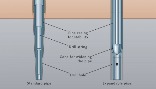
- 1.19 > To counteract the telescoping downhole reduction in well diameter, special new expandable pipes have recently begun to be employed. These are widened underground by pressing a hydraulically driven conical tool through the pipe. This technique is known as the solid expandable tubular method.
- With the first directional drilling methods it was initially only possible to drill at a predetermined specific angle. This involved incorporating a hydraulic motor into the front part of the drill string at the drill bit, whose axis was tilted a few degrees from that of the drill string. With this technique, as before, the drill string was driven from the drill rig. When the hydraulic motor was switched on, the drilling direction was diverted according to the pre-set angle. Because the angle only constituted a few degrees, the well was diverted in a broad arc. The curvature was so slight that the drill string was only minimally bent.
Furthermore, a special kind of steel was employed in the pipe so that it could bend slightly without breaking, like a drinking straw that can bend a little without crimping.
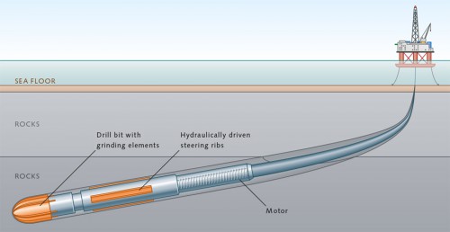
With modern directional drilling techniques, however, it is possible to adjust the direction while drilling. For this method, a steering unit with steering ribs, the steering sub, is mounted behind the drill bit. It is fitted like a ring around the drill pipe, which is driven from the drill rig. The steering ribs are hydraulically activated to press against the wall of the hole and wedge the steering sub. This produces a force that diverts the drill bit from its path. By activating the appropriate steering ribs it is possible to direct the drill bit in any desired direction. Sensors monitor the spatial position of the drill bit as it advances. A computer program corrects the course automatically as necessary. The motors and generators for the hydraulic system are located directly behind the steering sub.
- Today, with extended reach wells, drilling firms are able to drill horizontally to distances greater than 12 kilometres. Furthermore, from a horizontal well it is possible to branch off to other wells. This is called multilateral drilling. These horizontal wells diverge and bifurcate like the root system of a tree, ensuring maximum extraction from the reservoir.
Extended reach drilling can also be used from a land base to extract resources from offshore reservoirs. These methods have been used already for many years for oil production on the German North Sea coast, for example, as well as in current projects in the Caspian Sea.
For successful drilling it is important to flush the drill hole with an aqueous solution. Not only does the solution transport the drill cuttings away from the bit, it also cools the bit. Furthermore, due to its own weight, the solution produces a counter pressure that supports the drill hole to prevent caving. The aqueous solution is pumped through the drill string down to the drill bit, where it then enters the space between the drill pipe and the surrounding rock. It rises to the surface again inside this space.
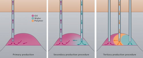
- 1.20 > Oil production can be broken down into three phases: During primary production, oil flows into the well under its own natural pressure. Later, pumps maintain the flow of oil. In the secondary phase, water is pumped into the reservoir to artificially increase formation pressure. To prevent the water from flowing past the oil into the well, the tertiary production phase involves injection of a polymer between the water and oil. Alternatively, the viscosity of the oil can be reduced by pumping in hot water or solvents.
 But the fluid is not able to protect the hole indefinitely against caving. For this reason steel pipes are intermittently cemented in the drill hole to support the walls. The problem with this is that the drill bit has to continue to advance deeper, and new pipe joints have to be pushed through the part that is already cemented. The subsequent pipe joints, then, have to have a smaller diameter than the cemented pipe. The hole is thus reduced in size downhole like a telescope. A well may have a diameter of up to 70 centimetres at the surface and, at a depth of several kilometres, have a diameter of only a little more than 10 centimetres. For future extraction at high rates, however, a large diameter is more effective.
New pilot projects are therefore employing flexible steel pipes. When they are in place, a hydraulic piston, called a conical expansion tool, is pushed through the pipe to widen it, creating a pipe with a uniform diameter.
Extra Info When scarcity struck – the oil crises

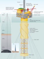 1.21 > Floating platforms like this spar buoy in the Gulf of Mexico are employed today for producing oil from especially great depths. To reach the reserves it is necessary to overcome not only the water depths, but also to drill almost equally deep into the sea floor, as shown in this example. To illustrate the scale, Burj Khalifa in Dubai, the highest building in the world, is shown in the figure.
When oil dries up
In essence, the same techniques are employed when drilling for gas or for oil. The extraction process, how- ever, is different for the two resources because oil is viscous and only flows to the well naturally for a limited time as long as the reservoir pressure is high enough. The flow dries up as the reservoir empties and pressure drops. The reservoir pressure must then be artificially increased by technological methods. Thus, three clearly distinct phases of oil production can be characterized:1. PRIMARY PRODUCTION
During primary production the oil initially flows to the well under its own natural pressure. When the reservoir pressure decreases and the oil flows more slowly, pumpjacks are deployed to pull the oil up to the surface. With primary production, only around 5 to 30 per cent of the original oil present in the reservoir, on average, can be extracted.2. SECONDARY PRODUCTION
To better exploit the reservoir, secondary production methods are employed following the primary production phase. The most common method is flooding with water. In this approach, water is injected under pressure into the side of the reservoir to force the oil toward the well. The reservoir pressure is artificially increased by pumping in the water. In rare cases, natural gas is pumped into the reservoir. This is generally only done in regions where natural gas is available in abundance. The valuable natural gas is later recovered. Secondary production increases the proportion of extractable oil to as much as 45 per cent of the reservoir.3. TERTIARY PRODUCTION
At some point, the secondary production methods reach their limit. Because water and oil have similar densities, it can happen during secondary production that the injected water flows past the oil and into the well, with the result that very little oil is produced. For this reason, tertiary methods are used to decrease the viscosity of the oil. Hot water or solvents are pumped into the reservoir for this purpose. Alternatively, it is possible to stop water flowing around the oil by introducing a synthetic liquid, a polymer, into the area between the oil and water. This polymer is so viscous that the water cannot flow through it. The pressure of the injected water is thus transferred through the polymer to the oil, forcing the oil out of the reservoir. Furthermore, additives are now being developed that will increase the viscosity of the water. This could also prevent the water from flowing past the oil.
Tertiary methods are also referred to as enhanced oil recovery (EOR) techniques. They are applied today to open up oil fields again that had previously been shut down because production had become uneconomic. Although they are more expensive than primary production, the EOR techniques have become economically viable due to rising oil prices. With tertiary methods, up to 60 per cent of the original oil in a reservoir can be extracted. This means that the pore spaces in a reservoir can never be completely emptied of oil, in part because of physical forces that hold the oil in the pores. Around 40 per cent of the oil remains underground whichever method is used. According to oil industry estimates, enhanced oil recovery techniques accounts for about 4 per cent of worldwide oil production today. It is believed that this could rise to 20 per cent by the year 2030. This is because many oil fields around the world will be so extensively exploited that it will be necessary to switch to tertiary methods. In natural gas deposits, the reservoir pressure similarly decreases when the gas is extracted. To retrieve the remaining gas, however, it is in most cases sufficient to employ pumps to suck the gas out and thus achieve the maximum yield.
1.27 > A wide variety of drilling and production platforms have been developed in recent decades for the extraction of natural gas and oil from the sea. These can be classified into different categories.
FIXED PLATFORM COMPLIANT PLATFORM
 FLOATING PLATFORM

Powerful technology for great depths
In their search for new gas and oil reserves in the sea, energy companies have penetrated to ever greater water depths. This was partly in response to the oil crises of the 1970s, which prompted the development of new deposits, for example in the North Sea. Many reservoirs on land and in shallow shelf areas near the coasts have been depleted or are already in the enhanced oil recovery phase. Interest in new reservoirs in the deep sea is thus increasing. In the 1940s the first gas and oil rigs were built in less than 10 metres of water on piers or ramps connected to the land. Later, platforms were built standing fixed on the sea floor. Some of them are so tall they would tower over the Empire State Building in New York. Today’s rigs extract gas and oil from water depths of almost 3000 metres. Because the construction of fixed rigs in water deeper than 400 metres is laborious and expensive, floating rigs are commonly used today for wells in great depths.
Specialists differentiate here between drilling and production rigs. Drilling rigs are used to open up a gas or oil field. Floating drill platforms are often used to drill down to the reservoir. They are then towed to their next deployment area. Alternatively, there are also large drilling ships which, in contrast to platforms, do not have to be towed but can travel from one reservoir to another under their own power.
When the drilling of a well is finished, it is initially capped at the sea floor with a wellhead. This is a kind of sealing cap, approximately the size of an automobile, that prevents the gas or oil from escaping. Only then can the drill platform be moved away. Later a production platform will be installed in its place. Then the wellhead is opened again and the natural gas or oil is extracted from the reservoir.
In moderate water depths, production rigs today are still erected with legs planted on the sea floor. At greater depths, however, floating platforms are employed. In addition, there are production ships, known as Floating Production Storage and Offloading Units (FPSOs). These are especially flexible and are often deployed for smaller gas and oil deposits. When one reservoir is exhausted they travel on to the next one. Rigs are also in use that can be employed for both drilling and production.Small industrial cities at sea
Whether it’s a drilling or production rig, a platform standing on the sea floor or a floating platform, each of these rigs is like a small industrial city. There can be fitness and conference rooms on board, bedrooms and lounges for up to 200 workers, and of course the equipment for drilling or production. On drilling platforms, this includes, first of all, the drill rig with the derrick, through which the drill string is lowered into the rock formations. The drill string is rotated either by a power unit in the derrick or by a rotary table directly on the platform, a kind of rotating disc with the drill string secured in the centre. There are also pumps that force the drilling fluid into the well.
For production, on the other hand, pumps are needed to draw the gas and oil to the surface when the reservoir pressure starts to drop. Because the resource is always mixed with sand and water, there are facilities on deck that separate and process the conglomeration. In addition, there are tanks for gas and oil as well as pumps to transport the resource to land by pipelines or to fill tanker ships. The power supply for the many items of equipment and for the living quarters is produced by generators.
Because oil usually contains a small amount of natural gas, processing systems are also required on oil production platforms to separate the gas from the oil. In the past, gas was usually flared off and wasted. Unfortunately, that is sometimes still the case today. But now it is being put to use more often, in many cases for generating electricity on drilling and production platforms. If it accumulates in large amounts it is pumped to land via pipeline.
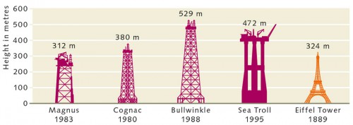
- 1.22 > Over time, oil production continued to shift further out to sea. Because the drill platforms still stood on the bottom, they had to be ever bigger and taller. Today, at greater depths floating platforms are mainly used.
- Today there is a large variety of standing or floating drilling and production rigs that have been developed for particular applications. They fall into three categories, as follows: FIXED PLATFORM: This type stands on legs on the sea bottom. Fixed platforms include:
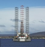 1.23 > The jackup drilling rig Constellation II is commonly used in the development of natural gas fields off South America. While under way, its legs are raised and loom above the platform like towers.
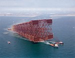 1.24 > The lattice framework construction of the Bullwinkle platform was prefabricated on land and towed into the Gulf of Mexico in 1988.
-
- Jackup rigs: Jackup rigs are large floating platforms with extendible legs. Cranes, living quarters and drilling or production systems are installed on board. They are brought to their destination by towboats or under their own power. Once a jackup rig has arrived at its site of deployment, the legs are lowered to the sea floor so that the platform stands on the bottom. The advantage is that when a job is finished the platform can be towed to a new location. The drilling platform Constellation II shown in Figure 1.23 is an example of a jackup rig. Among other tasks, it is used to drill test wells for natural gas.
- Steel platforms: Steel platforms are built on lattice framework towers. The steel frame possesses the special advantage of having low resistance to wind and waves. Steel construction is often seen in the Gulf of Mexico and in the North Sea. The pipes used to anchor the tower on the sea floor are several metres thick because they have to support a weight of tens of thousands of tonnes. The largest platform of this type is the Bullwinkle oil platform, which was erected in 1988 in the Gulf of Mexico as a production platform. It is a full 529 metres tall. The water depth at its deployment location is 412 metres. The steel construction was fabricated on land and then towed out to sea. Steel structures the size of Bullwinkle shown in Figure 1.24 are only used as production platforms in large and high-yield gas or oil fields.
- Concrete platforms: Concrete platforms rest on top of giant hollow bodies made of reinforced concrete. Because of their size and costly construction, they too are mainly used as production platforms in large gas or oil fields. Because of the very high water pressure at great depth, the hollow bodies are spherical or cylindrical in form. They are fabricated on land and then towed to the deployment location. They are partially flooded to prevent the structure from tilting. Enough air remains within the hollow space, however, for the structure to remain stable in the water like an enormous ship. At its site of deployment, the entire structure is then lowered to the sea floor. Later, during production, the hollow bodies can be used as tanks to store extracted gas and oil. A good example of this type of platform is the Sea Troll natural gas production platform, which began operations in the Norwegian Troll gas field in 1996. The 472 metre structure was fabricated on land and then towed out to sea. The water depth at the site is 303 metres.
- COMPLIANT PLATFORM: There are also variants of this platform type, such as steel towers that are supplemented with steel cables to anchor them to the sea floor. The following are especially common:
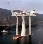 1.25 > The Norwegian Sea Troll is the largest natural gas platform in the world. It was moved to its deployment area by several towboats.
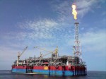 1.26 > The FPSO Kizomba A is part of a large oil production complex that consists of a production platform and several subsea units.
-
- Tension-leg platforms: The tension-leg platform (TLP) is one of the most common types of compliant platform. As a rule, it consists of a platform resting on a large buoyancy tank with multiple supports. Thus the TLP is not in fact a tower standing on the sea floor, but is permanently anchored to the bottom by thick steel cables. It is special in that the steel cables are kept tightened, so that the TLP remains stable in the water. The cables are tightened by partially flooding the buoyancy tank so that the structure sinks downward. Next the steel cables are installed. Finally, the ballast is pumped out again and the TLP floats upward. As a result, the tension in the steel cables between the sea floor and the buoyancy tank is increased. Because the buoyancy tank lies deep in the water, even in storm conditions the TLP does not move like a ship, which rides with the waves. The waves simply roll past under the platform and around the cables. Because a tower fixed on the sea floor is not necessary, this type of structure also offers the particular advantage that it can be employed for natural gas and oil fields located in greater water depths.
- Spar buoys: Closely related to the tension-leg platform is the spar buoy construction type. These are not tethered by multiple cables, but are supported by a long cylindrical hull that stands vertically like a giant pipe in the water. This hull provides lift like a buoy. This type has only been used in oil production for the past 20 years or so. An advantage of this configuration is that its thin cylindrical shape offers little resistance to currents in the sea and so it is not severely stressed by them. The cylindrical hull contains tanks for gas and oil as well as ballast tanks that can be used to raise and sink the spar buoy structure in a manner similar to a TLP. Like the tension-leg platform, the spar platform is anchored to the sea floor with permanently embedded tethers. The term “spar” is not an abbreviation, but simply refers to its being based on the cylindrical structure, in analogy to the round wooden or metal spars on a sailboat.
- FLOATING PLATFORMS: The floating platforms include small semi-submersibles that are held in position through their own power or by simple anchors. These platforms usually do not have a permanent anchoring system in the sea floor like the TLPs. They are frequently moved to new reservoirs for drilling operations. The floating platforms include drill ships as well as the FPSOs. These are usually deployed near production platforms or subsea facilities with which they are connected by flowlines or cables. Processing facilities for gas and oil are often present on the FPSOs, as well as large tanks from which tanker ships are usually filled. One example is the 285-metre long FPSO Kizomba A shown in Figure 1.26, which is deployed off Angola for oil production.
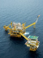 1.28 > Production platforms have been a part of the offshore oil and gas industry for decades. Important production regions include the coastal waters off South America and West Africa and, as seen in this photo, the Gulf of Thailand.
-
Production technology on the sea floor
Today, gas and oil production operations are no longer limited to using large platforms on the sea surface. There is now an alternative, known as subsea completion systems. These comprise various water-tight components such as compressors, pumps and separators for gas and oil processing mounted on steel frames. The components are placed directly on the sea floor. With the help of underwater robots, they are then connected together to form large production ensembles. Such subsea completion systems are not considered to be platforms, and thus effectively form their own class of offshore facility. They will generally be deployed in deep and ultradeep areas.
Subsea equipment has a number of advantages. For one, the systems work more efficiently when the pumps and compressors are closer to the source, which is on the sea floor, and for another, it is possible to clean and process the gas- or oil-water-sand mixture locally without having to pump it to the drill platform. This means that the production technology is much simpler and saves significant costs.
In addition, thanks to underwater technology, less production equipment is needed in large gas and oil fields. Even using directional drilling methods from a drill platform, the radius in which extraction can take place remains limited. However, if the pumps and compressors are emplaced directly on the sea floor, it becomes possible for gas and oil from numerous wells in a wide radius to be pumped to a common production station. From that station, the product can be sent onshore or to an FPSO, for example.
These kinds of subsea installations are now in operation in the Gulf of Mexico, off South America, West Africa and Norway. In the Perdido oil field in the Gulf of Mexico, for example, individual oil platforms at the water surface are connected to as many as 30 wellheads on the bottom. A single platform can thus produce oil from a number of wells.
- 1.29 > Gas and oil in deep water are increasingly being extracted with subsea systems that are located on the sea floor. These are modular systems. The individual components such as wellheads or compressors are linked to ensembles by flowlines.
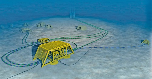
- In the Ormen Lange gas field on the Norwegian continental shelf, on the other hand, around 50 wellheads have been installed in an area of almost 500 square kilometres on the sea floor. These are connected to a small number of common subsea production stations under water that pump the gas onshore via pipeline. For these kinds of projects, new special equipment and machines are constantly being developed. Today, there are already underwater compressors on the market that are capable of increasing the pressure in natural gas reservoirs when they begin to empty and the formation pressure decreases, thus allowing continued production.
The development of subsea equipment remains a challenge because the various working parts and the electronic components not only need to be watertight and withstand high water pressures; they must also be highly reliable. On offshore platforms, compressors, pumps and compactors can easily be maintained, but with systems at great water depths, this is less straightforward. There, a defective machine would be a serious problem.
Work is therefore being carried out around the world to develop robust systems that will function around the clock for many years. The elements of such systems include compressors that pump natural gas into the pipelines. Compressor bearings are normally lubricated with oil. In subsea equipment, however, electronically controlled magnetic bearings, in which the axle floats, are now in use. The processing of oil and gas by means of subsea systems has reached a state of maturity at which it generates over 20 billion US dollars, and according to experts, this figure could double by the year 2020.